
Increasing part complexity directly drives up manufacturing costs. Complex parts require multi-axis CNC machines, longer cycle times, extra setups, and strict inspection.
When making just 5 or 10 prototypes, these design details might not seem like a big deal. But when you scale up to 500, 1,000, or 10,000 parts, even tiny DFM optimizations can save you huge amounts of money.
To help mechanical engineers and procurement teams optimize part design and shorten production cycles, Here is a simple DFM (Design for Manufacturability) guide to help engineers optimize designs and cut CNC costs.
Quick Takeaways: Key Factors Driving CNC Machining Costs
• Machining Time: Deep cavities, thin walls, and tight tolerances slow down spindle speeds and feed rates.
• Tooling & Setups: Non-standard internal features require expensive custom tools or multiple part flips.
• Material Waste: Excessive cavity depth and non-standard geometries increase raw material waste.
1. Avoid Thin-Walled (thin-wall thicknesses)Designs
Thin walls vibrate easily during cutting. This makes it hard to hold tight tolerances and often causes part deformation or breakage.
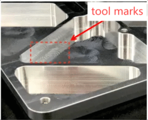
(Wall thickness design guide for CNC machined metal and plastic parts)
Thicker walls offer better stability and lower costs. Metal parts should have a wall thickness greater than 0.8mm, and plastic parts greater than 1.5mm.
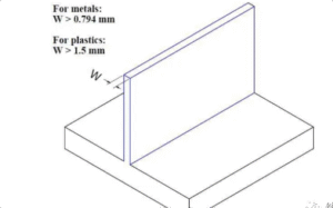
(Wall thickness design guide for CNC machined metal and plastic parts)
2. Avoid Features Unsuited for CNC Machining
Standard CNC cutters are round, so they cannot easily cut sharp internal 90-degree corners. If you really need square corners, you will have to use EDM, which costs a lot more. A cheaper way is to just add fillets to internal corners.
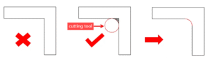
If you must have square corners for mating parts, you can also use relief cuts like dogbone or mickey mouse undercuts.
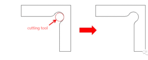
3. Design Larger Internal Corner Radii
Small corner radii require tiny end mills that cut very slowly. Keep internal radii as large as your design allows. A good rule is to make the radius at least 1/3 of the cavity depth.
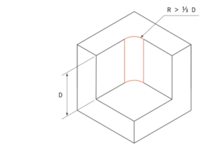 (CNC corner radius ratio)
4. Limit Cavity Depths
Deep pockets need long cutting tools. Long tools vibrate easily and force the machine to slow down. Try to keep your cavity depth within 4 times its width.
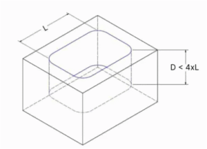
(CNC cavity depth limit)
5. Reduce Complex Surface Features
Complex 3D surfaces take hours to cut with small ball-nose tools. Simplify your shapes where possible. For instance, use flat chamfers on outer edges instead of rounded corners.
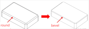 (CNC chamfer vs round bevel)
6. Limit Thread Lengths
Deep threads do not add extra holding strength, but they wear out taps quickly. Limit your thread length to 3 times the hole diameter max.
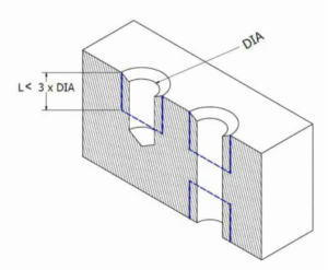
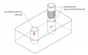
7. Design Holes with Standard Dimensions
Non-standard hole sizes force machinists to bore the hole with an end mill. Always stick to standard drill bit sizes so the operator can just drill it fast.
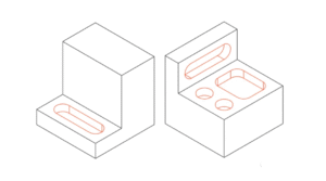
8. Minimize CNC Machine Setup Times
Flipping and re-clamping a part takes manual labor and risks alignment errors. Try to place as many features on the same side so you can machine them in one setup.
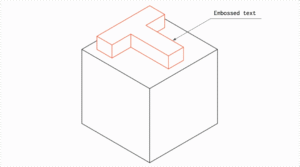
9. Avoid Unnecessary Text and Engraving
Cutting text into metal with tiny end mills takes forever. Skip CAD-machined text and use laser engraving or silk-screen printing instead.
Following these guidelines can help lower CNC machining costs without compromising the quality or precision of your parts.
Summary
Following these 9 DFM guidelines will dramatically lower your custom CNC machining costs without compromising functional precision or quality.
Ready to Optimize Your CAD Design for Manufacturing?
Unsure if your part design is cost-optimized? Upload your 3D CAD files (STEP/) to RB Rapid for a free DFM review and fast quote.